What is Heat Treatment?
Heat treatment involves the use of heating or chilling to achieve a desired result, such as hardening or softening of a material. Heat treatment techniques include annealing, case hardening, precipitation strengthening, tempering, normalizing and quenching.
In the heat treatment industry, there are typically two types of business, the first is captive heat treaters, who are part of a larger manufacturing facility and heat treat parts in house. The second type of business is commercial heat treaters, that provide heat treatment as a sub contracted service to various customers and markets.
Commercial heat treatment businesses process many different materials in various shapes and sizes. Sometimes the processes are multistage and undertaken in different types of furnaces to achieve the desired properties. This presents a number of issues, firstly it is fairly impractical and sometimes not possible to monitor the process for all of the parts being processed through a thermal cycle. Secondly, some of the heat treatment processes, if not undertaken properly will result in unsatisfactory properties. This may result in a requirement to retreat or scrap the material and as heat treatment is usually considered a finishing process the cost of scrapping these parts is high. This is particularly true for the aerospace and automotive industries.
So how do Process Engineers ensure that the equipment being used to process parts is fit for purpose? Testing the parts “post process” will tell them whether or not the treatment has been successful, but there is a need to know before processing the parts to avoid unnecessary scrap and rework. The answer is to establish a scheme of testing for the equipment that allows the furnaces to be classified, these classifications can then be adopted within process specifications. This in turn ensures that the equipment being used to process parts is operating efficiently and accurately enough to achieve a repeatable and consistent result that satisfies the end users requirements.These specifications for furnace classification are usually referred to as pyrometry specifications.
Pyrometry Specifications in the Aerospace and Automotive Industries
There are several specifications for pyrometry found within these two industries. For the aerospace industry there are examples such as BAC 5621 and RPS 953 that are written by OEM customers, there are also national standards such as BS 2M 54 and DIN 17052-1. The automotive industry has similar standards.
This article however will focus on the two that are the most widely adopted, for the aerospace industry (which is AMS 2750) and for the automotive industry (CQI-9).
Both specifications are broken down into sections that define requirements for instrumentation, the thermal processing equipment, the thermocouples, the thermal uniformity surveys (TUS) and the system accuracy tests (SAT).
Equipment Classification (Instrumentation)
CQI-9
Within CQI-9 the requirements for instrumentation are less stringent than AMS 2750. The key requirement is that the instrument controlling the furnace is calibrated and traceable to national standards. The temperature measured by the control instrument must also be logged by a separate recording instrument. Any more stringent instrumentation requirements are covered by the process tables A-H for specific processes. Within CQI-9 the process tables indicate the minimum tolerance requirements for specific processes (see appendices within CQI-9).
AMS 2750
AMS 2750 handles instrumentation in a more detailed way. Within the specification there are 5 instrumentation types A-E. The required instruments and sensors for each instrumentation type are described in the diagram below:
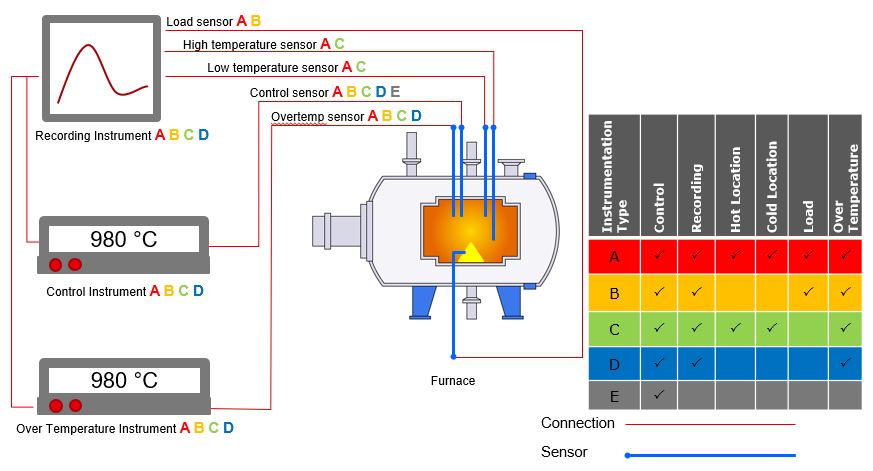
The definitions of each sensor type can be found in the figure above, within the specification.
Furnace Temperature Tolerance
The required temperature tolerance for any given product is normally defined within a process specification for the material or in some cases on the drawing. The temperature tolerance of a furnace is assessed by undertaking a TUS, which will be covered later in this article. Once established, this tolerance (and in the case of AMS 2750 the instrumentation class) affect the frequency and accuracy requirements of instrument calibration, future TUS and SAT tests.
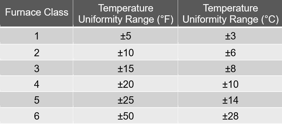
AMS 2750 does not indicate temperature tolerances to be used for specific processes but does tabulate tolerance bands to define furnace classes that are often referenced in process specifications as follows:
To see our handy scheduling tool for AMS 2750 follow this link: Pyrometry AMS2750
Thermocouples
Both Cqi9 and AMS2750 detail the calibration frequency and accuracy as well as usage limits for each type of thermocouple. The rules differ from CQI-9 to AMS 2750 and are dependent on the function of the thermocouple, as well as the thermocouple type and usage temperature.
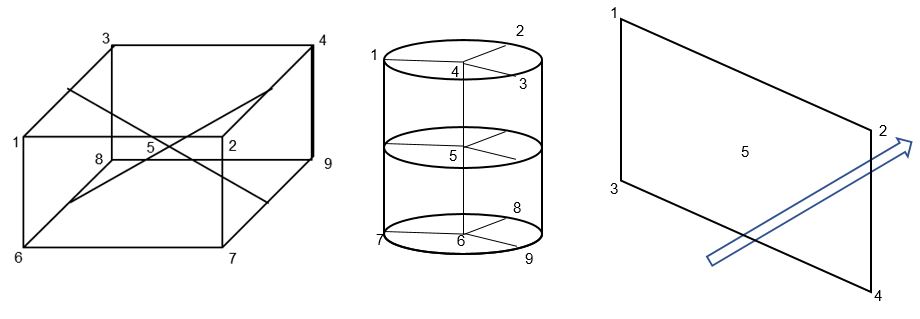
Thermal Uniformity Surveys (TUS)
Temperature Uniformity Surveys are undertaken to assess the temperature variation within the furnace work zone. Typical configurations for thermocouple positions can be box or cylindrical. The number of thermocouples required depend on the workspace volume and class of furnace. Specific Field Test instruments are used to record the TUS sensors (not the Process Recorder).
The survey requires a minimum of 30 minutes of good data (recorded at 2 minutes intervals or less). Except in the case of continuous furnaces which will be discussed later.
Diagrams of typical thermocouple configurations are shown below:
Key points during the survey (shown on the graph below)
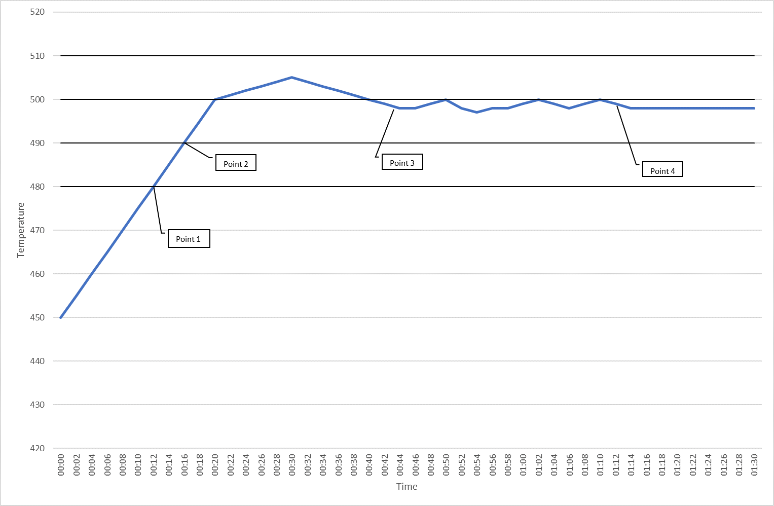
P1 – Start of monitoring. When first thermocouple crosses the monitoring threshold line. This point is a beginning of the trend and a first marker on the graph. Data is captured from this point.
P2 – When last thermocouple crosses the tolerance of setpoint.
P3 – Start of stability period. All thermocouples within tolerance and not trending away from the setpoint.
P4 – End of stability period. It's defined as P3 + measurement period. This point is the end of trend and the third marker on the graph. This is also end of data tables. A minimum of 30 minutes of data needs to be captured during the stability period.
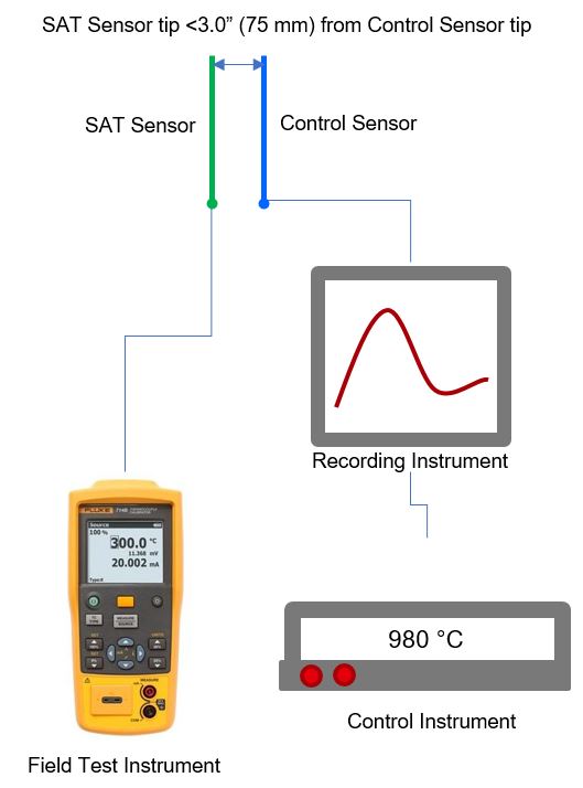
System Accuracy Test (SAT)
SAT is performed to assess the accuracy of the complete measurement system by using an independent device system (Field Test Instrument and calibrated SAT Thermocouple). By placing a test thermocouple in close proximity to the zone thermocouple, the delta provides a good indication of the ongoing accuracy of the thermocouple and instrument setup.
Summary
The heat treatment processes used in the manufacture of parts for both the aerospace and automotive industries are well regulated by both industry and national standards. To comply with these regulations the process has to be accurately measured using calibrated traceable equipment and the results documented. In static or batch processes this can be undertaken with equipment outside of the furnace; however in many cases time can be saved using an "in process" profiler. In conveyorized heat treatment processes a pass through (in process) temperature profiler is considered to be the safest, easiest to use and most accurate solution.