Getting Infra-Ready - Temperature Monitoring of Rotary Kiln Shell
Dr. Martin Budweg, Fluke Process Instruments, outlines how rotary kiln life can be improved using Infrared Temperature Monitoring.
This article was originally posted in World Cement, June 2020.
When analyzing any cement manufacturing process, it is evident that one of the most critical steps takes place in the rotary kiln. When it comes to extending the life of this piece of equipment, as well as preventing any disastrous failures, it is imperative that operators understand the condition of the refractory material coating it. Since it is impossible to measure the inside of the kiln, looking at the outer surface is the only way to determine refractory condition. This can be accomplished with infrared technology and specially developed kiln scanning systems.
The makeup of a kiln
During the operation of the rotary kiln, flames can reach temperatures as high as 1900°C (3452°F) in order to heat raw materials to roughly 1500°C (2732°F). As a result, these materials become partially molten and undergo a series of physical and chemical reactions to become the primary constituent of cement. At the lower end of a kiln, the raw materials emerge as red-hot particles, called clinker. Rotary kilns are traditionally large steel pipes, several meters in diameter and up to 100 m in length (in larger facilities, however, kiln lengths of over 100 m are not uncommon). To protect the steel from intense heat, however, each kiln is lined with bricks composed of refractory material, which is typically a blend of various ceramic compounds.
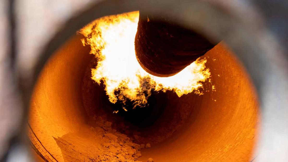
 A rotary cement kiln.
These refractory bricks have been compounded specifically for cement processing applications, and while they have impressive temperature and wear-resistance characteristics, exposure to intense heat and the abrasive qualities of cement inevitably leads to material degradation. This wear causes bricks to become thinner over time, severely impacting their ability to shield the steel surface of the kiln. In order to maintain adequate levels of protection, the kiln must be stopped at some point to replace the bricks.
Additionally, if a single brick, or a small section of bricks, becomes loose and falls, the steel kiln shell will suddenly be exposed to extreme heat. If action is not taken quickly, permanent damage to the kiln may result, costing facilities large amounts of money for repair or replacement costs, as well as countless hours of lost production time. By monitoring the entire length of the kiln shell, operators can easily determine the effectiveness of the refractory material. With infrared technology, any fallen bricks can be quickly detected, and appropriate action may even be taken to prevent further damage. Plus, by combining infrared temperature measurement with a database of historical images, operators can examine temperature trends and predict when refractory materials will reach unsafe operating conditions.
As a result, operators can schedule maintenance and plan when to replace the refractory material with minimal downtime. Continuous infrared temperature monitoring also allows the operator to see the overall effect of the process on the refractory, as settings can be optimised to maintain the best possible combination of maximum throughput and extended refractory life.
Understanding infrared scanning systems
Today, there are multiple temperature scanning systems for cement kilns available on the market, each with a variety of specifications and features; however, all of these systems utilise infrared scanning technology in order to gather temperature data.
To understand these scanning systems, operators need to know the basics of infrared technology. All objects emit infrared radiation; the intensity of this increases as the temperature of an object rises. Infrared temperature sensors used in industrial applications contain a detector that will generate a current when it is exposed to energy of a specific infrared wavelength. As the intensity increases, so does the current, allowing the temperature of the object to be determined.
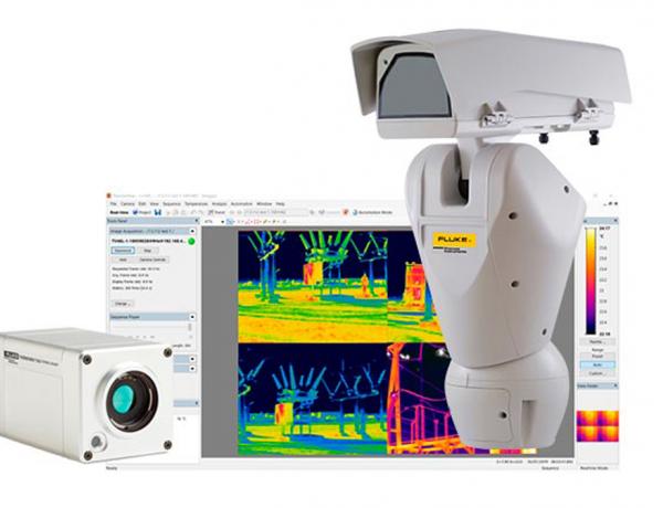
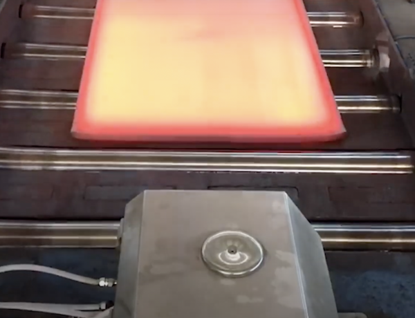
 The MP150 linescanner, which is used in the CS400 Cement Kiln Process Imaging System.
When monitoring rotary kilns, one or more linescanners (one of the more popular scanning systems available) often work in parallel to gather data along a kiln’s axis. As the kiln rotates, a new line of data is generated, allowing for the entire surface of the kiln to be mapped. The data is then transferred to application-specific software, which then converts raw data into a two-dimensional thermal image of the kiln’s surface.
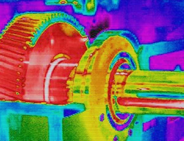
In addition to a two-dimensional image of the kiln, the software also displays each successive thermal image. This image is a ‘false’ colour representation of the kiln’s surface temperature; it is normal for cooler areas to be highlighted by darker colours and hotter areas to be showcased as bright red or white. Normally images are displayed in real-time for the operator, allowing for any significant changes to be seen quickly.
Images are also periodically saved to a history file for later analysis, meaning operators can use this data to predict the lifetime of refractory material and schedule replacements that keep downtime to a minimum.
Technology in kiln shell scanning
It is no secret that infrared technology has been widely embraced by the cement industry for more than 20 years; while all infrared rotary kiln systems offer the basic capabilities highlighted above, newer systems developed in the last decade feature some of the latest technology in the industry and offer expanded functionality to support operator needs.
Some top-tier functionalities, for example, address the concern of shadowed areas that stretch along the length of the kiln. With a wide field-of-view scanner, it can be common to have several obstructions, such as buildings, power poles, and other equipment, which essentially prevent the scanner from ‘seeing’ the entire kiln shell. Several of the top systems available today, for instance the CS400 System from Fluke Process Instruments, incorporate single point sensors, also known as pyrometers, that are located in such a way that they can ‘see’ the areas shadowed from the linescanner.
 A linescanning system positioned to monitor a rotary kiln tire slip.
Up to 32 pyrometers can be installed and set up to utilise multi-drop communication, meaning only one connection is necessary for communication back to a PC. Because the software integrates data from multiple sensors into one single image, a ‘dirty lens’ warning can be added. This feature compares each data point with its adjacent points and, if the difference exceeds the defined limits, operators are alerted that the sensor may be partially blocked by a dirty lens or other obstruction.
 A ‘false’ colour representation of the kiln surface temperature.
Additionally, top-tier scanning systems typically read frequencies between 3.5 μ and 4 μ. This range enables infrared linescanners to see directly through dust and moisture in order to determine the temperature of the kiln’s surface. In higher micron ranges, such as 8 μ to 14 μ, infrared systems tend to pick up reflections caused by dust and moisture in the air, meaning these solutions can only be used in more controlled facilities. As a result, linescanner systems are the ideal solution for cement manufacture in outdoor, rugged environments.
Other functionalities include monitoring clinker temperatures at the hot end of the process inside the kiln. In this application, an infrared sensor ‘looks’ into the hot part of the kiln end through a viewing port and monitors clinker temperature. The data is displayed on the same screen as the kiln shell imagery, allowing operators to monitor both steps of the process simultaneously.
Some systems, such as the CS400 System, also offer advanced capabilities that will monitor the condition of the brick and report on refractory wear. These software features also include a module database that can store and analyse all necessary data from (at least) the last year to indicate refractory wear during use, enabling engineers to schedule refractory repairs.
While these systems are useful, it is critical that the data entered into the programme by operators is accurate. Because all installations are inherently different, wear rates will also differ; therefore, making generalised predictions on the wear rate of any given material will inevitably lead to installations where the brick simply will not last as long as the system predicts.
One additional development in improving kiln life still utilises kiln monitoring systems, but not temperature measurement. Typically, kilns are driven from one end – which, due to their extensive size and mass, makes homogenous rotation extremely challenging. During this process, and particularly during speed changes, there is a tendency for some of the rotational energy to cause the kiln’s live-rings (or tire slips) to torque (or twist) instead of rotate.
A small amount of torque is not necessarily a problem for the live-rings, however, too much will cause damage to the fragile refractory material. In typical kiln monitoring systems, pyrometers are used to measure each live-ring rotation and trigger the display of each subsequent image of the kiln.
If multiple sensors are installed, the rotational speed of several points along the length of the kiln can be monitored – and if the rotational speed varies along the length, this can be indicative that a twist is occurring, allowing engineers to make corrections before serious damage occurs.
Conclusions
The purpose of monitoring kiln shells with an infrared scanning system is to monitor and report on the overall condition of the refractory materials lining the kiln. Most programmes available today offer some degree of refractory management and viewing this information alongside temperature data provides the information operators need to determine how to modify kiln settings to maximise refractory life or when to schedule downtime to replace bricks.
Infrared temperature scanning systems have shown their usefulness in cement plants across the globe and modern systems are adding even more functionality, making them an essential part of any cement professional’s toolkit.
About the authorDr. Martin Budweg is a Senior Product Marketing Manager at Fluke Process Instruments, where he is responsible for designing and developing IR temperature measurement products for a variety of industrial applications. Prior to joining Fluke, he worked in the chipset technology industry as a Project and Product Manager. Dr. Budweg studied Geophysics and Astrophysics and holds a PhD in Geophysics and Seismology.
For more information, see the following articles: