Deutsch | Español | Français | 简体中文 | 日本 | にほん

CS400 Banner

CS400 Kiln Shell Imaging System

Picture every brick in your kiln in real-time with continuous infrared monitoring.

CS400 Cement System Image
CS400 Cement System Software Image
CS400 Cement System Image
CS400 Cement System Software Image

Complete Kiln Monitoring

  • Avoid costly shutdowns with continuous hot spot detection on kiln refractory.
  • Reduce set up time with intuitive configurations and temperature profile calculations.
  • Optimize and manage maintenance schedules to extend the kiln’s operational life.

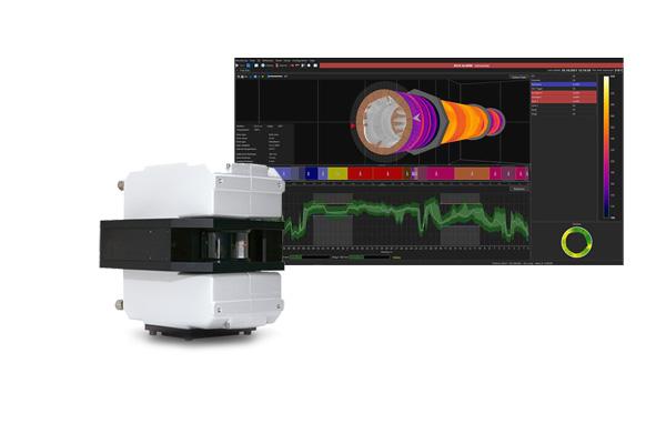
Picture every brick in your kiln in real-time with continuous infrared monitoring that can help prevent costly shutdowns and extend production runs. Specifically designed for harsh kiln environments, the CS400 Kiln Shell Imaging System is a fully integrated solution that continuously monitors kilns for hot spots – helping your team avoid costly damage and unscheduled downtime.

  • At a Glance
  • Technical Specs
  • Applications
  • Accessories
  • Resources

CS400 Linescanner System

The CS400 Kiln Shell Imaging System relies on the MP Linescanner, which provides continuous, accurate and real-time thermal images and temperature measurements for moving processes. With the ability to scan up to 1024 data points in a single scan, the MP Linescanner can provide a complete picture of even the highest speed manufacturing processes, ensuring an accurate temperature reading.

Key Features:

  • Multiple kiln support
  • Added ThermoView TV40 Thermal Imager support (Additional hardware required)
  • Added Pyrometer support – including Mi3 and Endurance units – for Burn Zone and Shadow monitoring (additional hardware required)
  • Analog and Digital I/O (Wago)
  • “One brick” resolution hot spot detection, even in shadowed areas

CS400 System Software

The CS400 Kiln Shell Imaging System features specially designed software, which relies on standard Ethernet ports. Because the graphic user interface is designed specifically for kiln applications, the software is easy to set up and use with little operator training required.

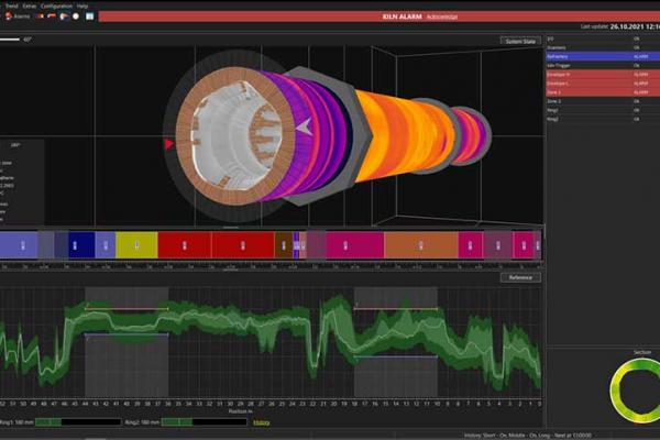
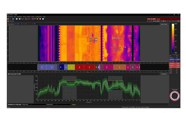
Once set up, the software provides a thermal image of the entire kiln shell surface, with a zoom function that allows detailed examination for key areas of interest. Temperature range and zone alarms can also be easily configured within the software and other information – such as burn zone temperature, lap time and the scanner’s internal temperature – is display in the status bar for a complete system status without changing screens.

Additional software options allow the kiln and refractory to be controlled and tracked through an integrated refractory management database and visualized in a live 3D view.

Key Features:

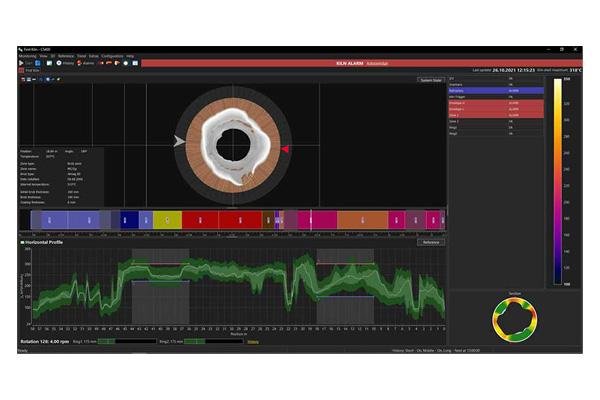
  • Polar charts highlighting coating thickness and brick thickness
  • Envelope profiles – including alarm functionality – over the entire kiln
  • Built-in, on-network storage to store historical data
  • Free scalable AOIs (areas, line and slice) including temperature trend analysis
  • Virtual 3D walkthroughs across the entire kiln
  • 3D views available per each defined kiln zone
  • Easy-to-use software configurations that showcase the scanner position relative to the kiln
  • Flexible image sizing and configurable orientations of rotation
  • Fail-safe “hot spot” alarm outputs
Feature Description
Temperature range 100 to 650°C (212 to 1202°F)
Temperature resolution 0.1 K
Accuracy ±0.5% of reading or ±3°C (±6°F)
Spot detection 510:1 (2.0 mRad IFOV) (50% energy)
Scan rate 1024 pixel per scan line (2048 for CS402)
Scan motor MTBF: 40,000 hours
Ambient temperature -40 to 45°C (-40 to 113°F) (without external cooling)
Position indicator temp. -25 to 230ºC (-13 to 446ºF)
Zone alarms Software: unlimited; Hardware: 3
Kiln rotation rate Up to 10 rpm
TSM accessory Supports up to 6 tires
I/O Modules 32 modules, up to 16 digital outputs per module
Burning Zone accessory Endurance Ratio Pyrometer 600 to 1800°C (1112 to 3272ºF), connection box, 15m high temp. cable, Thermojacket, blast gate, sighting tube, adj. pipe adapter, adj. mounting base, air flow/press. regulator
Shadow Monitor accessory MI3LTH Sensor -40 to 600°C (-40° to 1112°F) with 8m high temp. cable, air purge jacket and adj. mounting base.


Standards and Compliance

EC Directive 2014/30/EU EMC
EC Directive 2011/65/EU RoHS Compliance amended by Directive (EU) 2015/863
EC Directive 2014/35/EU Directive 2014/35/EU – low voltage
EN 61326-1: 2013 Electrical measurement, control and laboratory devices - Electromagnetic susceptibility (EMC)
EN 50581: 2012 Technical documentation for the evaluation of electrical products with respect to restriction of hazardous substances (RoHS)
EN 61558-2-6: 2010 Safety Requirements for power transformers, power supplies, reactors, and similar products for use up to 1.1 kV (low voltage)
EN 61558-1: 2006 Safety Requirements for power transformers, power supplies, reactors, and similar products (low voltage)

The CS400 Kiln Shell Imaging System is ideal for process monitoring and control for a variety of rotary kiln-based applications. Click here if you would like to speak with an expert to discuss your application.

Several examples of where this system can be used include, but are not limited to, the following list below:

Tire Slip Monitoring

The Tire Slip Monitoring (TSM) accessory records tire slips and can be configured to generate alarms with user-defined limits. This accessory is fully integrated with the CS400 System software and is capable of extensive historical data analysis.

I/O Modules

The optional I/O module hardware provides digital inputs and outputs, as well as analog outputs. These can be used for fan control and hot/cold alarms as necessary.

Burn Zone Monitoring Package

With the optional Burn Zone Monitoring Kit, operators can monitor the condition of the burn zone area directly with the CS400 System software. With the kit, temperatures are displayed alongside kiln shell temperatures. All data is recorded and stamped for later analysis. The kit includes a two-color ratio point sensor, which can “see through” combustion gases, protective housing and all the hardware necessary to complete the installation.

Shadow Sensor Package

The CS400 System software can accommodate select point sensors to monitor areas of the kiln shadowed from the main linescanner. This data is seamlessly integrated into a single thermal image – both for real-time display and for later data analysis. Our most used sensor and all necessary accessories are provided as a kit.

Get more information about CS400 Kiln Shell Imaging System
Welcome to Fluke's Chat GPT Assistant. As with other generative AI systems, this chatbot may occasionally generate incorrect information. For questions regarding the safe use of Fluke tools, please refer to your owners manual. You must comply with your employer’s safety standards and obtain necessary training before using Fluke tools or taking electrical measurements. To speak with a person, visit our Contact Us Page.
How can I help you today?