The thermocouple is one of the least complex of all sensors and as such it can be both rugged and low cost making it ideally suited for use in industrial applications.
It consists of two wires of dissimilar metals that are joined at the measurement point; referred to as the hot junction. The output from the sensor is a voltage proportional to the temperature difference between the hot junction and the cold end of the wires. The voltage generated is both very small and nonlinear, this presents design challenges for manufacturers of thermocouple instrumentation. However if the instrumentation is designed correctly the thermocouple provides a very low cost sensor that can be easily replaced if damaged.
Thermocouple Theory
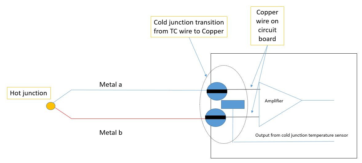
A thermocouple circuit has at least two junctions: the measurement junction (hot junction) and a reference or cold junction. The reference junction is the point where the two thermocouple wires connect to the measuring instrument (for example the datalogger). It is the point where the metals change - from the thermocouple metals to the metal in the measuring instrument which in most electronic data recorders is copper.
The output voltage from a thermocouple is related to the temperature difference between the measurement and the reference junctions. This is a result of a phenomenon observed by Thomas Seebeck in 1821, in which a circuit made of two dissimilar wires altered the position of a compass needle when one of the junctions was heated.
Each thermocouple type has its characteristic Seebeck voltage curve. The Seebeck curve is dependent on the metals used in the two wires of thermocouple and voltages generated are measured in mV. Almost all wires used in thermocouples are alloys and the homogeneity of the alloy is vital to the accuracy of the measurement system.
It is important to remember that the voltage is not generated at the hot junction but along the wire in the regions where there is a thermal gradient. Where best accuracy is required this should be considered when checking thermocouple accuracy prior to use.
Thermocouple Types
Thermocouples are divided into two basic groups; those constructed from base metals and those from noble metals. Base metals are lower cost elements typically copper, iron or nickel alloys. The exact ratios of metals in the alloys are not defined, but the voltage/temperature response curve is. So, at a microscopic level, base metal thermocouple wires from two different suppliers could have different ratios of metals. Noble metal thermocouples are constructed using expensive elements such as platinum and rhodium. The exact purity levels and ratios are defined, as are the voltage/temperature curves.
Some commonly used thermocouple types and their use range are listed below.
|
Thermocouple type |
Use range (excluding limitation of wire insulation) |
Wire composition |
|
Type K |
-270 to 1370C (-454 to 2500F) |
Ni-Cr (+ve ) and Ni -Al |
|
Type N |
-270 to 1300C (-454 to 2372F) |
Ni-Cr-Si (+ve ) and Ni-Si-Mg |
|
Type T |
-270 to 400C (-454 to 752F) |
Cu (+ve) and Cu-Ni |
|
Type J |
-210 to 1200C (-346 to 2193F) |
Fe (+ve) and Cu-Ni |
|
Type E |
-270 to 1000C (-454 to 1832F) |
Ni-Cr (+ve) and Cu -Ni |
|
Type R |
-50 to 1768C (-58 to 3214F) |
Pt-13% Rh (+ve) and Pt |
|
Type S |
-50 to 1768C (-58 to 3214F) |
Pt-10% Rh (+ve) and Pt |
|
Type B |
0 to 1768C (32 to 3308F) |
Pt-30% Rh (+ve) and Pt |
Thermocouple Construction
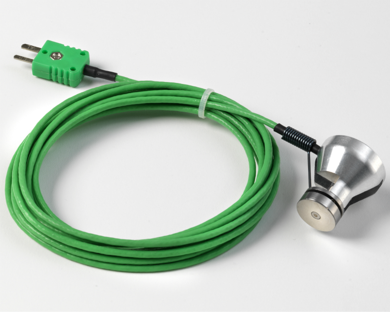
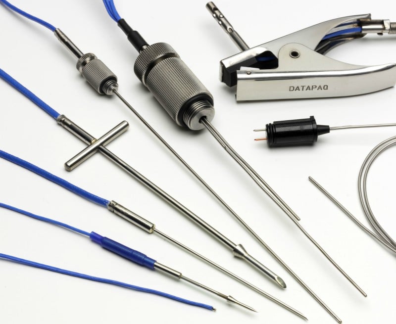
One key advantage of thermocouples is that being simple to construct it is possible to design them to match the applications; for example, in the food industry they can be pointed for easy penetration into product, while in metals heat treatment they can be welded to the product. Sensor tips can be flattened for better thermal contact or attached to magnets for quick installation
The wire insulation can be flexible such as PTFE or glass fibre braided for temperature resistance and at higher temperatures they can be supplied in metal or ceramic sheaths.
Thermocouple Instrumentation
Careful electronic and mechanical design of thermocouple instrumentation, such as dataloggers is required to ensure best possible accuracy. The mechanical design has to ensure that the cold junction sensor is isothermal with the point at which the thermocouple wires connect with the copper tracks/wires of the circuit board. If the cold junction sensor cannot accurately track the changes in temperature it will result in an error in the final measurement equal to the tracking difference. It is critical this area is free from thermal gradients.
With the voltage from the thermocouple being as low as 4uV/C amplification is required prior to digitization of the signal. Thermocouples are generally long parallel wires and are often used in electrically hostile environments where they will behave as an antenna picking up interfering signals; therefore careful electronic design is needed to filter out the unwanted signals.
Summary
Thermocouples are low cost, rugged and cover a wide temperature range it is estimated more than half of all temperature readings in USA industry are made using thermocouples. The output voltages are low and nonlinear but if the measuring instrument or data logger is carefully designed the measuring system can yield accurate and repeatable results.